OpenReflow Project
The OpenReflow project is an Open Source Hardware Reflow Oven Controller module that is designed to work with most 120v and 240v toaster ovens, to provide a consistent, reliable and flexible reflowing control.

The OpenReflow project is an Open Source Hardware Reflow Oven Controller module that is designed to work with most 120v and 240v toaster ovens, to provide a consistent, reliable and flexible reflowing control.
The design is inspired by the 'Reflowduino' project as when it came time for me to build my own Reflow Oven, the only suitable project was the Reflowduino, and I couldn't buy them any more, as they had been discontinued. Other projects existed, or I could have bodged one up using some relays or SSRs and an Arduino, however I wanted a complete and polished solution.
Many polished solutions for this exist on the market, however they were well outside my price range, and never wanting to miss an opportunity to build something, I put myself to work designing a new alternative. The birth of the 'OpenReflow' project.
Progress
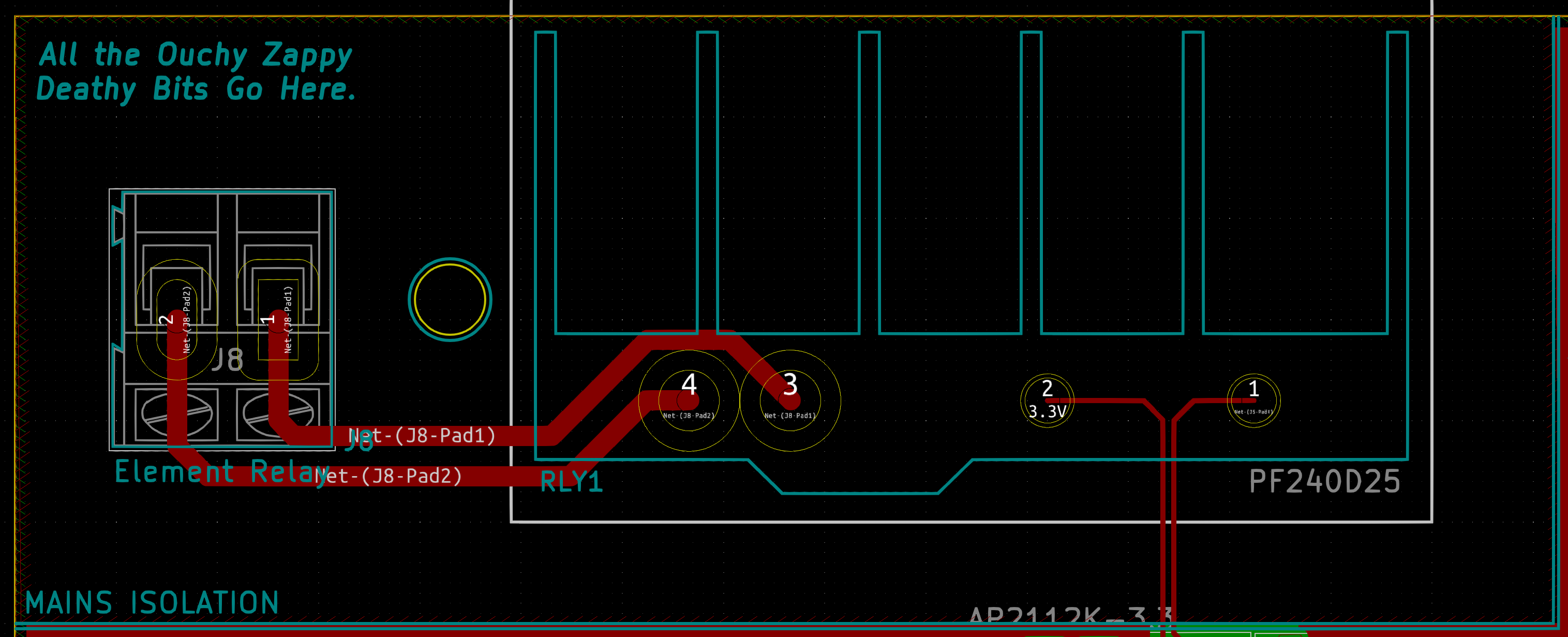
To date, I have completed the Schematic diagrams and the PCB layouts. The design is intended to fit inside a standard project box and doesn't require any heat-sinking aside from the sink that comes built into the SSR (solid-state relay) chosen for the design. The SSR is by far the most expensive component, however it is fully optically isolated and is very simple to drive and control. Considering we're playing with MAINS VOLTAGES here, I considered it prudent to go for a very safe option.
The project box is plastic so is safe for the board to be mounted in directly, and it is designed with screw terminals on the PCB to allow for a side-mounted Mains inlet and outlet plug to ensure we don't have to worry about cutting and splicing too many mains cables for the oven.
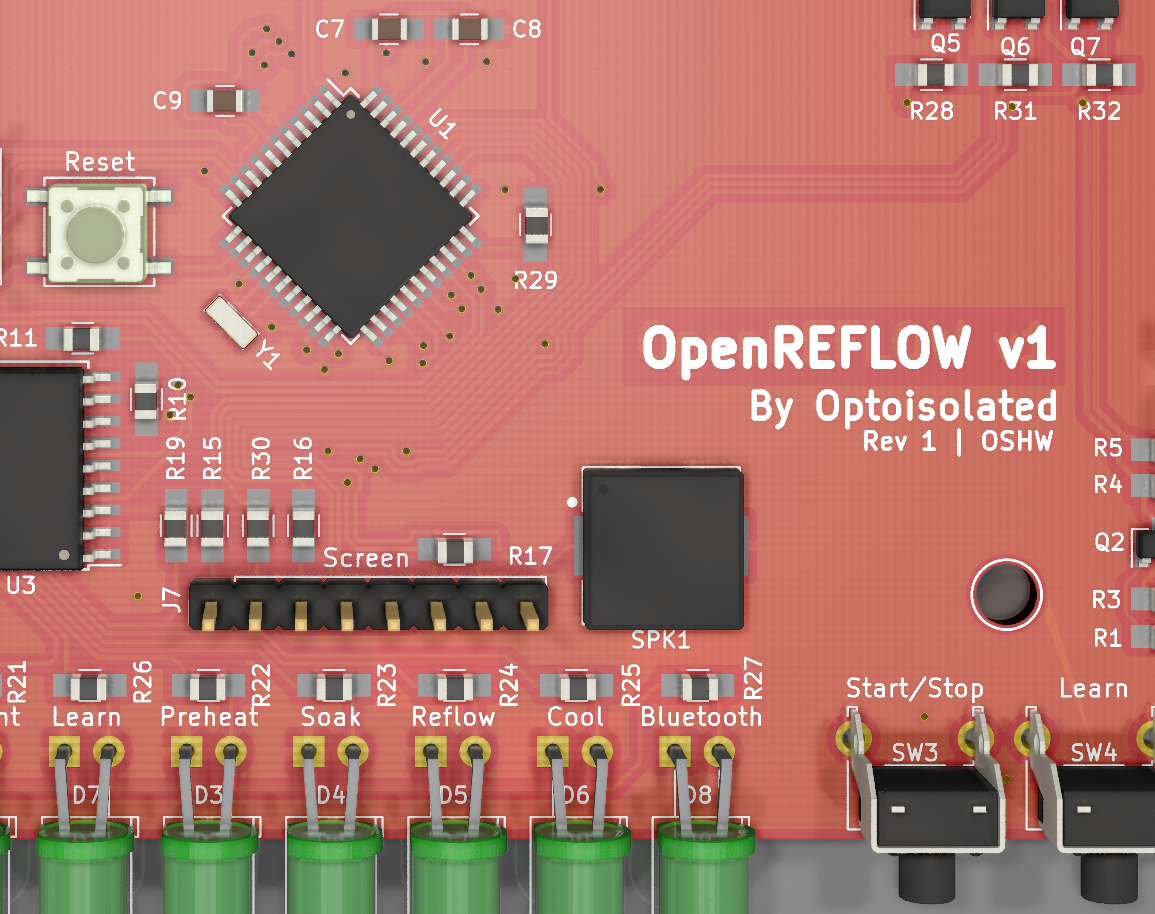
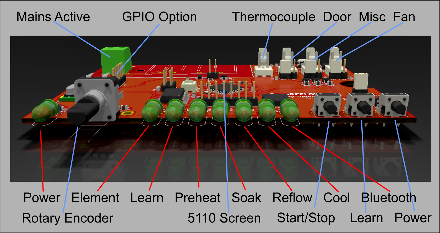
As for control, I hesitated on removing the Bluetooth BLE controller for the PCB, however as this was going to be an open source project, I opted to make the Bluetooth controller optional in the design. What I have introduced to the design which are novel are the standardised indicator LEDs for the reflow oven status and progress, power indications, a rotary encoder for navigation and control, independent button controls and lastly a Nokia 5110 display for showing temperature and graphing the profile. One of my favourite additions to this project is the use of a soft-power button to remove the need for a power switch, and allow for the micro-controller to automatically power down the unit in the event of an error or just as a power-saving measure.
Although the unit can be controlled from a PC or a phone/tablet, I wanted the OpenReflow to be able to be completely controlled independently of other hardware, so the on screen menus, buttons and rotary encoder mean that the entire unit can be fully configured and controlled without the Bluetooth module.
The best part of the design is it now has the capability for not just relying on arbitrary tweaking of timings for building the best reflow profile for each oven, it instead has a 'Learning' option, which allows the OpenReflow software to profile the oven and automatically adjust the profile timings for Preheat, Soak, Reflow, and Cooling to ensure temperature ramps are smooth, and we minimise overshoot.
While the current design does not support WiFi, Rev 2 of this project would include support for a Wemos D1 mini module to allow for WiFi control, howevert this wasn't included in Rev 1 for now, to keep it simple. There is ample board space for an additional module however.
I also wanted the native capability of the unit to be able to handle services such as automatically opening the door for cooling, running a circulation fan (for ovens that support it or I'm able to find a way to build it) and generic outputs for other switchable devices. For extra extensibility there is also a GPIO header with 1 analog IO, 2 digital IO, 3v3 and 5v outputs as well as ground. From this header almost any device imaginable could be easily integrated into the unit.
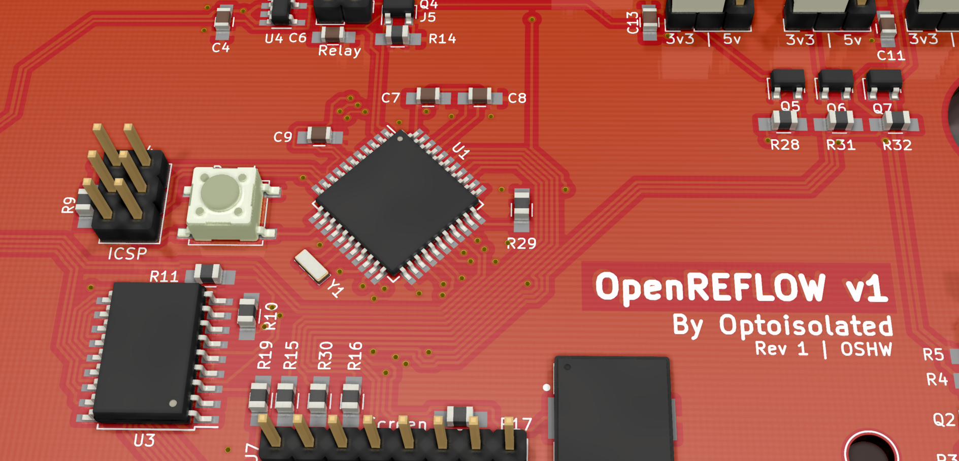
I chose the Atmel ATMega32U4 micro-controller to manage this project, as it has enough IO pins to do all of the critical services, as well as native USB support, so no tertiary USB driver circuitry is required. Unfortunately there wasn't enough IO for all of the LEDs and the display together so I've elected to add a single IO expander to drive the output LEDs.
The ATMega32U4 is fully compatible with the Arduino ecosystem, so it makes it ideal for an open source project, as it's easily mod-able, and the programming header is included in the board design. The OpenReflow software I am currently writing will be closed-source, but a fork of the ReflowDuino will be available on my Github which will fully support this unit, with the exception of the Learn function and some extra functionality available using the inbuilt menus.
I have not yet sent the boards off to manufacture as I like to leave it a week or two before doing so, as it allows me to review the design with a clear head and pick up any obvious errors in the design.
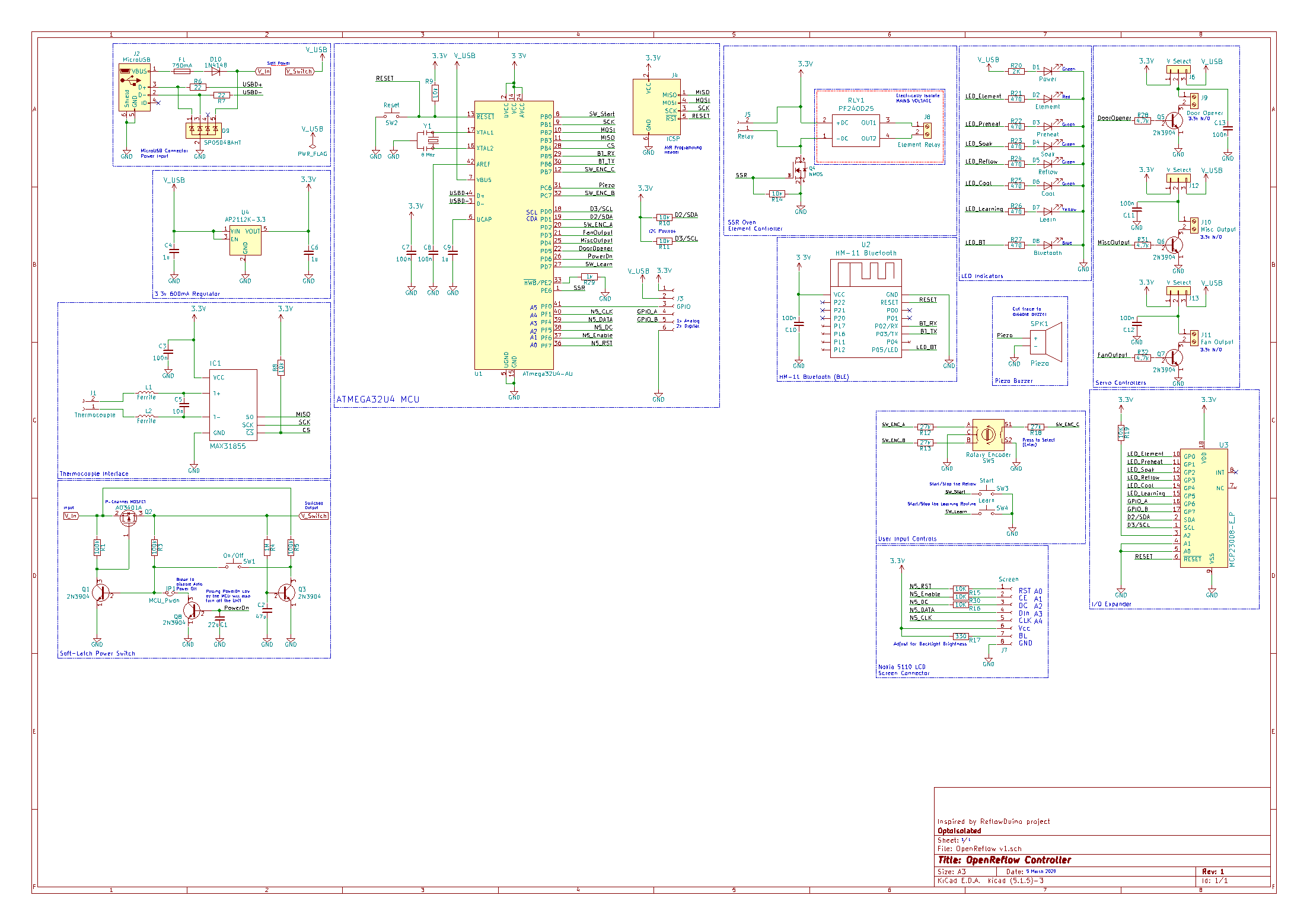
The Schematic
The schematic is open source, and available on my Github project page. The schematic for Rev 1 is shown below, and is fully designed using KiCAD 5.1.5-3.
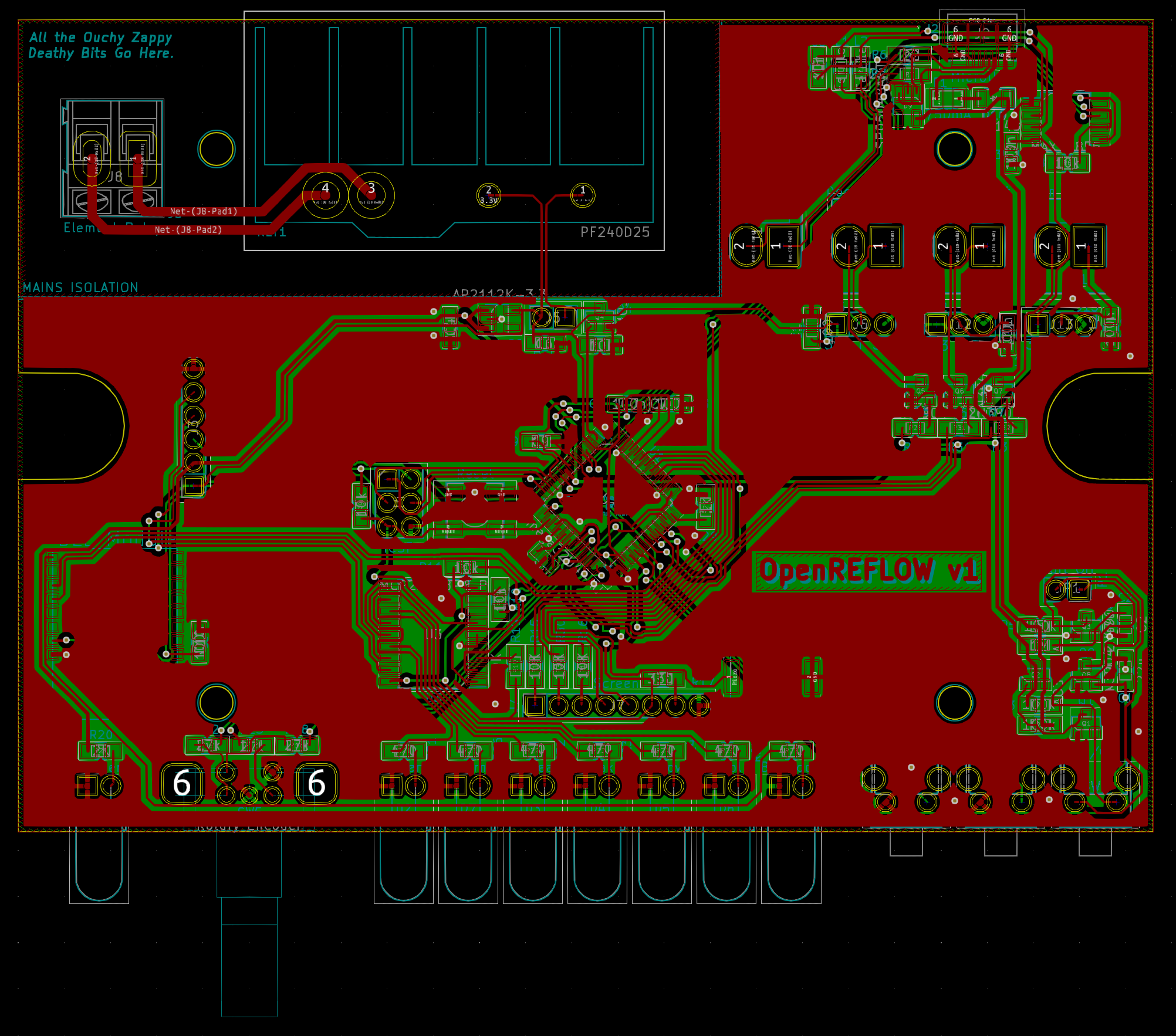
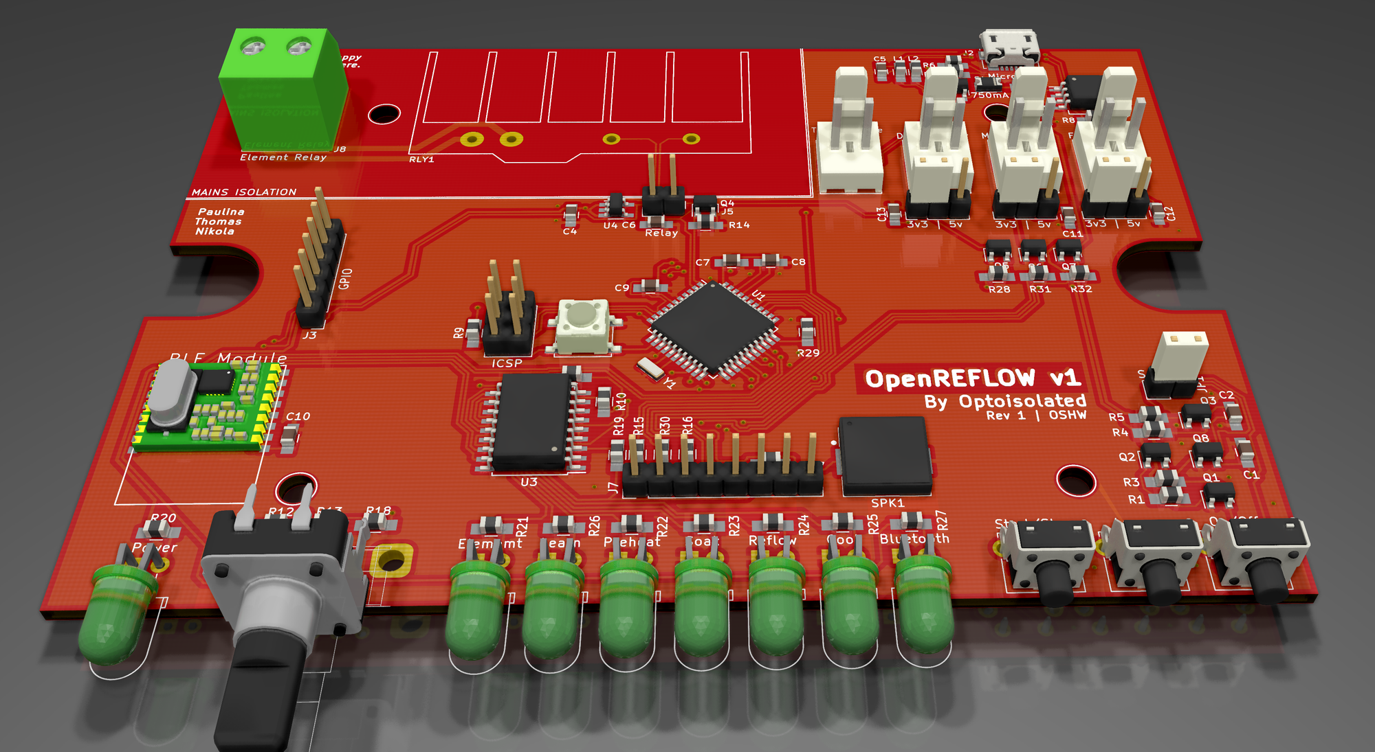
The PCB Layout
This PCB layout was a breeze to work on mostly due to the board being so large, there was ample room to lay everything out logically. It's not as clean as I'd like however as this is a prototype I am satisfied that once I lock down all of the components and their placement, that I will be in a better position to refactor some of the more messy traces, and work on minimising the number of back-PCB traces.
The Case and Mechanical layers
I wanted the project to use easily accessible parts where possible and fortunately there were many case options available that would suit this project. I considered the form factor size, the thermal impact of the SSR and airflow, as well as the accuracy of the thermocouple readings coupled with the cold-junction thermocouple driver. Based on that information, I selected the Ritec RM2015L ABS Instrument Case. It's quite a sizable case, on par with 12v battery chargers from the 90s, has a sizable volume which will be good for maintaining thermal equilibrium, and plenty of front panel surface area, suitable for the LEDs, buttons, rotary encoder and the 5110 display.
There is also more than ample space on the rear of the unit for the thermocouple connector, the GPIO, Control Outputs etc as well as the Mains Input and Output, and the USB connector, so all in all is an ideal case choice. Reviews of the case suggest it's very rugged and will serve as a secure enclosure for the project.
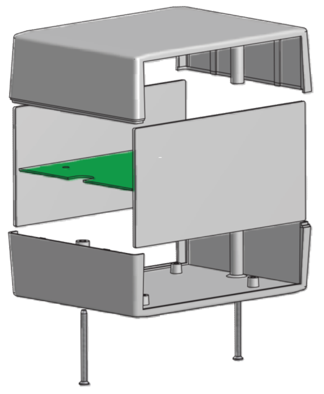
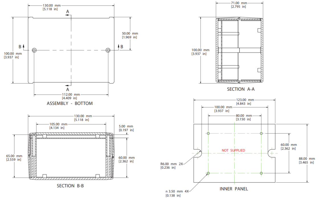
I am expecting that on the side of the Back panel where the SSR will be located that I will include cutouts for ventilation however I am still deciding if that is going to be necessary based on the likely amount of heat generated by the SSR.
Operation
The reflow oven controllers primary task is to deliver control of the heating element in the generic consumer grade toaster oven, in order for the temperature, not just inside the unit, but on the board itself, to follow the profile as shown in the image below. This profile is critical as it ensures the optimal flow of solder to the components, and minimises the amount of thermal energy that the parts and the board itself are exposed to.
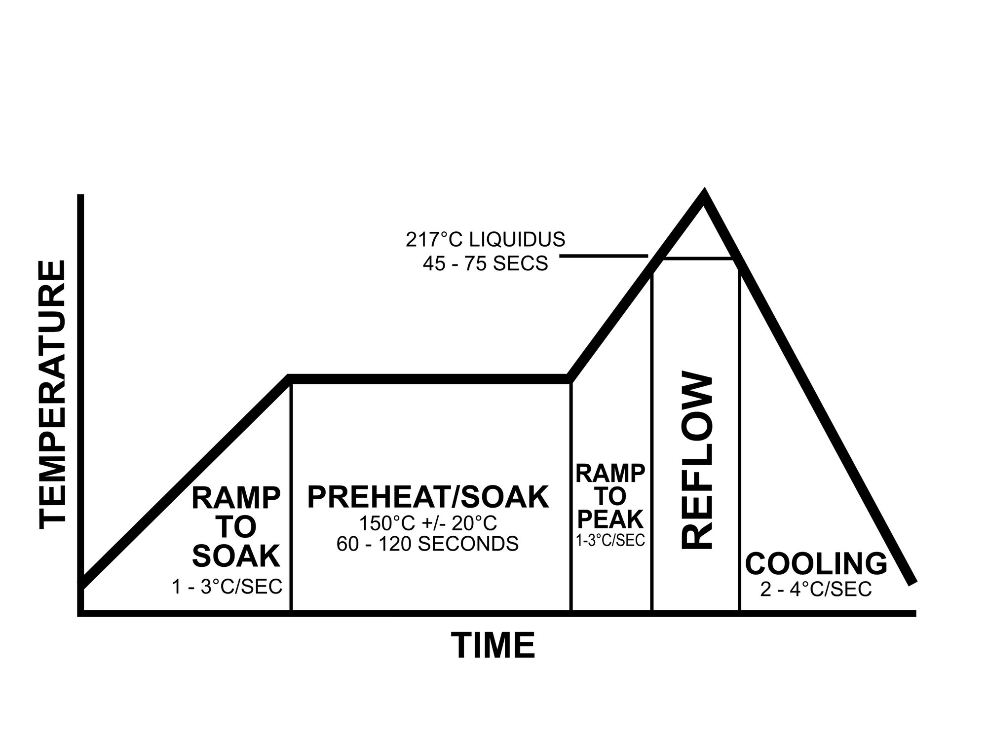
As every ovens temperature response is different, I've included some hardware capability for the unit to be able to learn how best to drive the oven to meet the temperature profile as closely as possible. When the unit is turned on, pressing the 'Learn' button will get the unit to ramp up to a set temperature, and then attempt to hold that temperature by intermittently turning on and off the element. By measuring this timing, it's possible to adjust the timings of the reflow temperature profile to best suit the oven the user is connecting to the unit. Ideally this would be done for every board, however running it every so often should be enough for most situations.
Once the profile is defined, it can be easily adjusted using the on-screen menus, or eventually using a mobile app via Bluetooth. The screen and the app would be able to view the current state of the unit as well as monitoring and controlling the unit remotely (but still nearby).
The door opener output is designed to trigger (not drive) a servo which would open the door slightly to more precisely control the cooling. Usually the ovens are very good at retaining heat, so opening the door slightly allows more heat to escape, and being able to automatically open and close the door allows the unit to more accurately control the rampdown temperature profile.
Issues
As yet this design has not been prototyped and may require significant modification to be suitable for a Rev 1 release, however so far it's looking like a very promising design.
Future Considerations
* Adding servo controller circuitry to drive the servos instead of just triggering them
* Modifying the unit to run from Mains AC instead of relying on a USB power source.
* Internal ventilation
* Built in Wi-Fi and Bluetooth support, with external antenna for the Wi-Fi
* Support for additional temperature probes
* Additional safety controls.
Conclusions
As the project develops, I will be adding more posts about it and including additional information in this page. Stay tuned.